
Downhole Thermal Management Practices
High-Temperature Oil & Gas and Geothermal Drilling
Key Questions Answered in This Article
How does downhole temperature limit drilling performance in HPHT and geothermal wells?
Why is temperature a more critical constraint than pressure in extreme wells?
What is bottomhole circulating temperature (BHCT), and how does it affect tool reliability?
How does insulated drill pipe reduce thermal exposure to downhole tools?
When is dual-wall insulated drill pipe required in geothermal and ultra-HPHT wells?
How much temperature reduction can surface mud cooling systems realistically achieve?
Why does stopping circulation cause rapid heat soak in high-temperature wells?
How do continuous circulation systems prevent temperature spikes during connections?
What is a staged trip-in, and how does it protect MWD, LWD, and RSS tools?
How do thermal jackets and vacuum flasks enable logging in extreme geothermal wells?
Introduction
As drilling operations move into deeper formations, hotter geothermal provinces, and more complex reservoirs, temperature has become one of the most critical limiting factors for drilling performance and tool reliability. Whether in deep HPHT oil and gas wells or high-enthalpy geothermal projects, excessive downhole temperatures place severe constraints on drilling tools, fluids, elastomers, electronics, and operational practices.
Unlike pressure, which can often be contained through mechanical design, temperature directly affects material strength, electronic stability, chemical reactions, and fluid behavior. As a result, drilling high- and extremely high-temperature wells requires not only specialized equipment but also carefully designed operational strategies to manage heat exposure throughout the drilling lifecycle.
This document provides a practical, industry-aligned overview of how high- and extreme-high-temperature wells are defined, where such environments are encountered, the temperature limits of modern drilling tools, and the techniques used to prevent tool failure. The intent is to give drilling professionals an understanding of thermal challenges and solutions.
Techniques to Avoid Tool Failure in Extreme High-Temperature Wells
Effective thermal management relies on reducing the temperature experienced by downhole tools or limiting their exposure duration. In practice, this is achieved through a combination of equipment design and operational discipline.
1. Insulated Drill Pipe (IDP)
Overview and Concept
Insulated drill pipe is designed to manage downhole thermal exposure by introducing a thermal barrier within the drill pipe wall. Unlike conventional drill pipe, which readily transfers formation heat into the circulating drilling fluid, IDP intentionally slows this heat transfer. The insulation is integrated into the pipe structure to maintain mechanical integrity while providing controlled resistance to conductive heat flow from the wellbore into the fluid column.
In high-temperature wells, particularly deep HPHT and geothermal environments, this thermal control becomes critical. As drilling fluid travels downward through the drill string, it is exposed to progressively hotter formations. Without insulation, the fluid rapidly absorbs heat, raising bottomhole circulating temperature (BHCT) that can exceed the operating limits of downhole tools and fluids. IDP moderates this process by limiting how quickly formation heat reaches the internal fluid stream.
How and Why It Works
The effectiveness of insulated drill pipe lies in its ability to decouple the thermal interaction between the formation and the drilling fluid while maintaining normal hydraulic circulation. As fluid flows down the drill string, the insulation slows radial heat transfer, allowing the fluid to reach the bottom hole at a significantly lower temperature compared to conventional drill pipe.
This temperature reduction is not necessarily dramatic in short sections, but its cumulative effect over thousands of meters is substantial. Even a modest reduction in heat gain per meter can translate into a meaningful decrease in BHCT. As a result, temperature-sensitive downhole components such as MWD/LWD electronics, rotary steerable systems, and elastomeric seals remain within acceptable temperature ranges for longer durations.
Additionally, by reducing rapid heating and cooling cycles during circulation changes or tripping, IDP helps stabilize the thermal environment of the drill string and bottomhole assembly.
Operational Impact and Value
From an operational standpoint, insulated drill pipe extends the effective drilling window in high-temperature formations. Wells that would otherwise require frequent circulation breaks, reduced ROP, or shortened tool run times can be drilled more efficiently.
Key operational advantages include:
Extended drilling exposure in hot sections, allowing longer on-bottom time before reaching tool temperature limits.
Improved reliability of MWD/LWD measurements, as electronics operate in a more stable and predictable thermal environment.
Reduced thermal fatigue in drill string components, caused by repeated expansion and contraction during temperature cycling.
Better drilling fluid performance, since lower fluid temperatures help preserve rheology, lubricity, and chemical stability.
2. Dual-Wall Insulated Drill Pipe
Design Philosophy and Concept
Dual-wall insulated drill pipe builds on the same thermal management principles as conventional IDP, but adds an additional layer of thermal resistance. Instead of relying on a single insulation barrier, this design incorporates a secondary annular space or structural separation between the inner flow path and the outer pipe wall. This configuration further disrupts conductive heat transfer from the formation into the drilling fluid.
The dual-wall concept is specifically intended for extreme temperature environments where conventional insulation alone is insufficient. These include deep geothermal wells and ultra-high-temperature HPHT wells, where formation temperatures can exceed 250 °C and thermal gradients are severe.
This design is particularly effective in long open-hole intervals or extended exposure scenarios, where cumulative heat pickup would otherwise push BHCT beyond tool and fluid limits. The dual-wall structure also helps maintain a more uniform temperature profile along the drill string, reducing localized thermal spikes.
Practical Application and Operational Significance
Dual-wall insulated drill pipe is most commonly applied in wells where thermal constraints are the primary drilling limiter, rather than mechanical or hydraulic factors. In geothermal drilling, for example, it enables longer drilling intervals between circulation stops and significantly improves the survivability of downhole tools.
Operationally, the use of dual-wall IDP can:
Enable drilling in formations previously considered beyond conventional tool temperature limits
Reduce the need for aggressive surface cooling or excessive circulation rates
Improve overall drilling efficiency by minimizing temperature-related nonproductive time
Because of its specialized design and higher cost, dual-wall insulated drill pipe is typically deployed in targeted sections of the drill string and justified through thermal modeling and well-specific risk assessments.
3. Surface Mud Cooling Systems
Overview and Concept
Surface mud cooling systems are designed to actively remove heat from the drilling fluid after it returns from the wellbore and before it is pumped back downhole. In high-temperature drilling environments, the returning mud can reach temperatures that rapidly push downhole tools toward their thermal limits if recirculated without cooling. Mud cooling systems interrupt this cycle by lowering the fluid temperature at the surface, thereby reducing the heat carried back into the well.
These systems are commonly deployed in HPHT oil and gas wells and are standard practice in many geothermal drilling operations, where managing thermal exposure is critical for tool survival and operational continuity.
How Mud Coolers Reduce Fluid Temperature
Mud coolers operate on conventional heat exchange principles, transferring thermal energy from the drilling fluid to a secondary cooling medium. The most widely used configurations include plate heat exchangers, shell-and-tube exchangers, and air-cooled radiators, selected based on mud type, flow rate, and available utilities.
In a typical setup, the hot return mud is diverted through the cooling unit, where it flows across heat exchange surfaces. On the opposite side of these surfaces, a cooler medium such as fresh water, seawater, or ambient air absorbs heat from the drilling fluid. This process lowers the mud temperature without altering its composition or rheological properties.
In water-based mud systems, water-cooled heat exchangers are particularly effective due to favorable thermal conductivity. For oil- or synthetic-based muds, exchanger design is optimized to handle higher viscosities, prevent fouling, and maintain efficient heat transfer.
Typical Temperature Reduction Achieved
Mud-cooling systems used in high-temperature drilling environments typically reduce the surface return fluid temperature by tens of degrees Celsius before it is recirculated. Commercial and field examples show temperature reductions of 20–50 °C (36–90 °F), with many systems achieving 30–40 °C (54–72 °F) cooling under normal drilling circulation rates. The achievable drop depends on mud flow rate, cooling capacity, the type of cooling medium, and the operational configuration.
While these reductions occur at the surface, their impact is magnified downhole. A decrease of even 15–20° surface temperature can translate into a similar or slightly reduced reduction in bottomhole circulating temperature, depending on well depth and thermal gradient. Over long circulation periods, this shift can mean the difference between operating safely within tool limits and exceeding critical temperature thresholds.
Downhole Impact and Operational Significance
Lowering the surface mud temperature effectively resets the circulating system's thermal profile. As the fluid travels down the drill string, it continues to absorb heat from the formation, but from a cooler starting point. This delays the onset of high bottomhole temperatures and reduces the peak thermal exposure experienced by the BHA, MWD/LWD tools, and motors.
Practical Value in High-Temperature Wells
Surface mud cooling systems offer several practical advantages in high-temperature drilling environments:
They provide direct and adjustable control over circulating fluid temperature.
They reduce thermal stress on downhole tools, extending operational time between failures.
They improve the stability of drilling fluid properties by limiting thermal degradation.
They complement downhole thermal-mitigation methods, such as insulated drill pipe and continuous circulation systems.
Because mud-cooling systems are surface-based, they can be deployed or scaled with minimal impact on downhole hardware, making them a flexible, widely applicable solution in both oil and gas and geothermal drilling operations.
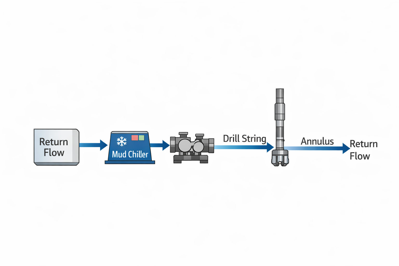
Fig: Mud Cooling Loop
4. Continuous Circulation Systems
Overview and Concept
In conventional drilling operations, circulation must be stopped during connections, leaving the drilling fluid static. During these pauses, heat from the formation rapidly conducts into the drill string and bottomhole assembly, causing a temperature increase commonly referred to as heat soak.
Continuous circulation systems are designed to eliminate this interruption by maintaining fluid flow while making connections. By ensuring uninterrupted circulation, these systems prevent the sudden temperature rise that typically occurs during static periods.
Why Continuous Flow Matters Thermally
Downhole temperature behavior is strongly influenced by whether the fluid is moving or static. When circulation stops, convective heat removal ceases, and the BHA temperature begins to approach the formation temperature. Even short pauses can cause sharp temperature spikes, particularly in high-gradient wells.
By maintaining circulation, continuous circulation systems keep heat transfer in a controlled, dynamic state. The moving fluid continuously removes heat from the BHA and surrounding components, preventing localized overheating and maintaining a more uniform temperature profile throughout the drill string.
Operational Impact
The primary thermal benefit of continuous circulation is stability. Instead of repeated heating and cooling cycles associated with connections, the downhole environment remains relatively constant. This is particularly important for temperature-sensitive tools, which are often more vulnerable to rapid temperature changes than to steady-state high temperatures.
Continuous circulation systems are most beneficial in wells where frequent connections coincide with high formation temperatures, making them a valuable tool in extended-reach, deep, and HPHT drilling operations.
5. Automated and Optimized Temperature Management
Overview and Concept
Advances in drilling automation and digital monitoring have enabled a more proactive approach to thermal management. Modern drilling systems increasingly rely on real-time temperature modeling that integrates surface measurements, downhole sensor data, and wellbore geometry to predict temperature behavior throughout the drilling system.
Rather than reacting to overheating after it occurs, these systems allow operators to anticipate thermal exposure and make informed adjustments before temperature limits are exceeded.
How Real-Time Optimization Works
Temperature models continuously update as operating conditions change, accounting for factors such as depth, circulation rate, mud properties, and drilling mode. Based on these inputs, the system can forecast bottomhole temperatures during drilling, circulation, and tripping events.
This predictive capability supports operational decisions such as adjusting flow rates to enhance convective cooling, optimizing drilling fluid characteristics to improve heat transport, or modifying tripping practices to control heat soak during static periods.
Operational Benefits and Reliability Gains
The greatest value of automated temperature management lies in its ability to reduce uncertainty. By understanding how temperature will evolve before it becomes critical, drilling teams can operate closer to tool limits without exceeding them.
This approach delivers several practical benefits:
Fewer unplanned tool failures caused by unexpected thermal exposure
Improved confidence in long drilling runs in high-temperature sections
Better coordination between drilling, fluids, and directional teams
Reduced nonproductive time associated with temperature-related interruptions
As wells continue to push deeper and hotter boundaries, automated temperature management is increasingly becoming a core element of well planning and execution rather than a supplementary tool.
6. Staged Trip-In and Controlled Circulation
Thermal Risk During Trips in High-Temperature Wells
When drilling in high-temperature environments, managing the temperature of downhole tools isn’t only important while actively drilling; it becomes critical during trips, especially when tools are being run into the hole. In extremely hot formations, circulating drilling fluid continuously keeps the bottomhole assembly (BHA) cool. But when drilling stops, especially during a trip, temperatures at depth can rise quickly toward the static formation temperature because the moving fluid no longer removes heat. This rise can occur surprisingly quickly, bringing electronic components, elastomeric seals, and tool housings close to, or even beyond, their design limits if left unchecked.
Thermal Behavior When Circulation Stops
Under static conditions, heat transfers from the formation into the wellbore and tools by conduction, so the temperature of the static fluid and nearby equipment rises toward the surrounding rock temperature. Field data from wellbore temperature measurements confirm that when fluid circulation stops, bottomhole temperatures climb significantly within short timeframes, sometimes rising by over 10 °C within an hour, because the cold-circulation effect is lost and the wellbore fluid equilibrates thermally with the formation.
This phenomenon is particularly pronounced in geothermal and HPHT wells, where formation temperatures at depth are often well above the safe operating limits of downhole electronics and elastomers. For tools rated for 175–200 °C maximum, even modest static temperature increases can quickly push conditions into failure-risk territory.
What Staged Trip-In Is and Why It Matters
Staged trip-in is an operational practice developed to manage this thermal risk. Rather than running the entire drill string to the bottom hole in one continuous motion, the trip is broken into shorter intervals. After lowering the BHA and drill string to an intermediate depth, the drilling team pauses to circulate fluid before continuing deeper.
At each pause, circulating cool drilling fluid removes heat accumulated in the BHA and fluid column. This controlled circulation helps keep the BHA temperature within an acceptable range before the next segment of the trip.
Practical Implementation of Staged Trip-In
In practice, staged trip-in is integrated into the drilling program during high-temperature sections or when bottomhole circulation temperatures approach instrument limits. The specific intervals for pausing (e.g., every 3–10 stands of drill pipe) depend on well depth, the formation temperature gradient, and the temperature tolerance of the tools being run.
During each pause:
Drilling fluid is circulated at normal or elevated pump rates to maximize convective cooling.
Surface chillers and mud coolers may be used in tandem to ensure the circulating fluid is as cool as possible.
Downhole temperature telemetry (when available) helps confirm that the BHA has returned to a safe range before proceeding deeper.
Controlled Circulation Integration
While “staged trip-in” breaks the run-in process into segments with circulation pauses, controlled circulation refers more broadly to managing fluid flow to minimize thermal spikes even during connections and trip operations. Continuous circulation systems (where mud flow is maintained while making connections) are one example; staged trip-in manually applies that same principle in a segmented way during run-in.
Together, staged trip-in and controlled circulation complement other thermal management techniques. When combined with insulated piping, surface cooling, and real-time thermal modeling, these practices form a comprehensive strategy for preserving tool integrity and drilling efficiency in high-temperature wells.
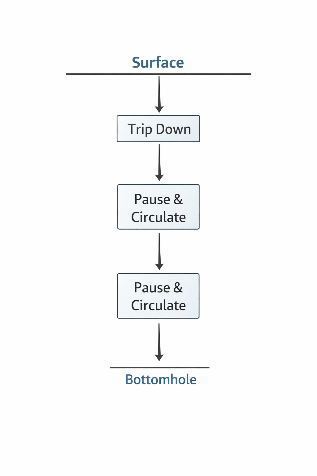
Fig: Staged Trip-In
7. Thermal Jackets and Vacuum Flasks
When logging tools are run into high-temperature wells, whether on wireline, slickline, memory runs, or during short formation evaluation operations, they are directly exposed to the hot formation and hot drilling fluid. Unlike Measurement-While-Drilling (MWD) and Logging-While-Drilling (LWD) tools that benefit from continuous fluid circulation to manage temperature, many logging operations involve static or slow movement in the hole. In these situations, the risk of overheating is significant because heat from the formation conducts rapidly into the tool housing, posing a threat to electronics, batteries, sensors, and other temperature-sensitive components.
To extend the operational window and enable tools to survive long enough to complete measurements, the industry commonly uses thermal jackets and vacuum flasks as passive thermal protection systems.
How They Work
Both thermal jackets and vacuum flasks are designed to slow the rate at which external heat enters a tool rather than actively cooling it. They create layers of insulation between the hot wellbore and the internal tool components.
A thermal jacket is essentially a high-performance insulating cover that wraps around a tool or a section of the tool body. Its purpose is to reduce conductive and convective heat transfer to the tool housing, buying time before internal temperatures approach critical thresholds.
A vacuum flask, sometimes called a Dewar flask, is a more advanced form of insulation that operates on the same physical principle used in laboratory flasks and consumer thermoses. It consists of a double-walled enclosure with the space between the walls evacuated. The vacuum dramatically reduces heat transfer because there are no gas molecules to conduct or convect heat through the wall space, and reflective surfaces further minimize radiative heat transfer. This creates an insulating barrier that keeps the internal chamber cooler far longer than a solid metal housing alone.
Once enclosed in a vacuum flask, sensors, circuit boards, and batteries inside the tool are less exposed to the ambient wellbore temperature. In practice, this means that a wireline or memory-based logging tool can remain in a well that is several hundred degrees Celsius at depth without overheating for the duration of the logging run. The limited run time, often only a few hours for memory tools and up to a day for some wireline tools, is a key reason this approach is effective and widely used.
Practical Field Effectiveness
Thermal jackets and vacuum flasks do not lower the well’s bottomhole temperature itself. Instead, they delay the temperature rise within the tool by slowing heat flow. This delay is critical: it allows tools to collect data, make measurements, or complete runs during a controlled time period before internal temperatures reach unsafe levels.
In practice, several field examples demonstrate how vacuum flasks enable logging in environments that would otherwise destroy tools:
Industry projects have tested vacuum-flask-based tool designs at bottomhole temperatures above 350 °C to 450 °C, with significantly extended operational windows compared with unprotected tools.
Manufacturers routinely offer vacuum-insulated housings for wireline production logging tools, with some designs capable of maintaining internal temperatures below critical limits for dozens of hours, long enough to perform detailed surveys in high-temperature geothermal or HPHT wells.
Typical Use Cases and Limitations
Thermal jackets and vacuum flasks are most commonly used for:
Wireline logging operations in wells where static temperature exposure is unavoidable.
Memory-based tool runs, where tools collect data internally without real-time telemetry, and must survive the entire logging interval.
High-temperature geothermal wells, where wireline tools must be deployed into zones with sustained high formation temperatures that exceed the normal ratings of tool electronics.
Specialized logging runs, such as casing integrity surveys or production profiling, where downhole time is limited but exposure to extreme heat is inevitable.
However, these systems have natural limits. They only delay heating, not eliminate it, and once the internal temperature rises above a tool’s rated limit, the tool must be brought back to the surface for cooling and servicing. Vacuum flask protection is therefore designed to match the expected duration of the logging run, not indefinite deployment.
They also add physical length and some weight to the tool string, and their effectiveness diminishes as downhole temperature approaches levels where traditional electronics cannot operate, even with prolonged insulation.
Thermal Management Decision Map
Tool- and Practice-Selection Guide
If the dominant risk is cumulative heat pickup while drilling:
→ Insulated Drill Pipe (IDP)
→ Dual-Wall Insulated Drill Pipe
If the dominant risk is high surface return mud temperature:
→ Surface Mud Cooling Systems
If the dominant risk is heat soak during connections:
→ Continuous Circulation Systems
If the dominant risk is tool exposure during trips:
→ Staged Trip-In with Controlled Circulation
If the dominant risk is static exposure during logging operations:
→ Thermal Jackets
→ Vacuum Flasks
In most cases, a combination of multiple strategies is used and recommended to manage thermal risks in drilling high-temperature oil and gas and Geothermal wells.
Frequently Asked Questions – Downhole Thermal Management
What makes high-temperature drilling different from conventional drilling?
High-temperature drilling is primarily limited by tool and fluid temperature ratings rather than by pressure containment. Excessive heat affects electronics, elastomers, drilling fluid chemistry, and tool reliability, making thermal management a critical part of well design and execution.
What is the most effective way to reduce bottomhole circulating temperature?
Bottomhole circulating temperature is typically managed through a combination of insulated drill pipe, surface mud cooling systems, and controlled circulation practices. No single solution is sufficient in extreme environments.
Why do downhole tools fail during connections in HPHT wells?
During connections, circulation stops, and convective cooling ceases. Heat from the formation rapidly transfers into the bottomhole assembly, causing temperature spikes commonly referred to as heat soak.
Are vacuum flasks used to cool downhole tools?
No. Vacuum flasks do not actively cool tools. They delay heat transfer into the tool, extending the time available for logging or measurement before internal temperatures reach critical limits.
Why is staged trip-in important in geothermal and HPHT wells?
Staged trip-in allows intermittent circulation during trips, preventing rapid temperature rise under static conditions and protecting temperature-sensitive electronics and elastomers.
References:
Schlumberger. 2016. "The Defining Series: HPHT Wells." Oilfield Review, March 10.
International Association of Drilling Contractors (IADC). 2025. "IADC Geothermal Well Classification." IADC, February 17.
Finger, J.T., and Blankenship, D.A. 2010. "Handbook of Best Practices for Geothermal Drilling." Sandia National Laboratories, SAND2010-6048.
Tester, J.W., et al. 2006. "The Future of Geothermal Energy." Massachusetts Institute of Technology, MIT Press.
van Oort, E., et al. 2022. "Downhole Heat Management for Drilling Shallow and Ultra-Deep High Enthalpy Geothermal Wells." Geothermics, Volume 105.
Aydin, H., and Merey, S. 2021. "Potential of Geothermal Energy Production from Depleted Gas Fields: A Case Study of Dodan Field, Turkey." Renewable Energy, Volume 164.
Chatterjee, K., et al. 2015. "High-Temperature Logging While Drilling Tool." NETL, DOE Project.
Wu, W., et al. 2025. "A Comprehensive Evaluation of Drill Pipe Insulation for Downhole Temperature Control." Stanford Geothermal Workshop, February 10.
Baker Hughes. 2020. "Drilling Services Quick Reference Guide." Baker Hughes, September 4.
Weatherford. n.d. "High Pressure High Temperature LWD." Weatherford International.
API Technical Report 1PER15K-1, Protocol for Verification and Validation of High-Pressure High-Temperature Equipment.
IADC Geothermal Well Classification System, IADC, Feb. 17, 2025.
Smithson, T., “HPHT Wells,” Oilfield Review, Schlumberger, 2016.
“High Pressure/High Temperature (HPHT) Wells,” RCPAT, 2025.
Turn0Search2, “New Geothermal Wells Exploit Unconventional Technology,” Oil & Gas Journal, 2025.
Turn0Search19, GA Drilling, Insulated Drill Pipe (IDP), 2025.
Zhang, Y., Ashok, P., Chen, D., and van Oort, E., 2026, Tripping and Staging into Geothermal Wells while Assuring Thermal Protection of Downhole Tools and Sensors, Geothermics, Volume 136, Article 103598, Elsevier. https://www.sciencedirect.com/science/article/pii/S0375650526000039