Toolface Orientation in Directional Drilling
Key Questions Answered in This Article
What is toolface, and why does it matter in directional drilling
Differences between magnetic toolface and gravity toolface
When and why directional teams switch between modes
How toolface affects steering decisions with mud motors and MWD systems
Best practices for measurement and error avoidance
What Is Toolface and Why It Matters
In directional drilling, precise control of the well trajectory depends on knowing exactly where the deflection mechanism in the bottom-hole assembly (BHA) is pointing at any moment. Whether the BHA includes a bent sub, a steerable mud motor, or a rotary steerable system, the direction in which that bend or steering mechanism is oriented determines how the wellbore will deviate as drilling progresses. This directional reference is known as toolface.
Toolface is defined as the angular orientation of the BHA’s steering element relative to a fixed reference frame. By controlling toolface during drilling, particularly while sliding with a mud motor, the directional driller can deliberately build, drop, or turn the well to follow the planned trajectory. Because even small orientation errors can translate into significant wellbore deviation over distance, accurate toolface measurement and interpretation are essential for maintaining well placement, minimizing corrective work, and avoiding excessive torque and drag.
Toolface orientation is measured downhole by the survey sensors in the Measurement-While-Drilling (MWD) system and transmitted to the surface in real time. These measurements allow the directional drilling team to monitor the BHA's actual steering direction and make timely adjustments to stay on plan.
2. Magnetic and Gravity Toolface: Why Two Systems Are Used
Two different reference systems are used to define toolface orientation: magnetic toolface (MTF) and gravity toolface (GTF). The need for two systems arises from changes in well inclination as drilling progresses.
In near-vertical wells, gravity does not provide a strong or reliable reference for defining the “up” direction of the borehole. As inclination increases, however, gravity becomes the dominant and most intuitive reference for steering. For this reason, magnetic toolface is used early in the well, while gravity toolface is used once sufficient deviation has been established.
3. Magnetic Toolface (MTF): Orientation in Near-Vertical Wells
Magnetic toolface is typically used in vertical and near-vertical sections of the well, where inclination is generally below about 5 to 8 degrees. At these low inclinations, the borehole lacks a clearly defined high and low side, making gravity-based orientation unreliable.
In magnetic toolface, the reference direction is magnetic north. Magnetometers in the MWD tool measure the Earth’s magnetic field to determine azimuth, while accelerometers account for any minor inclination or tilt of the tool. The measured magnetic azimuth is then corrected for local magnetic declination to align the reading with true north if required by the well plan.
Magnetic toolface is expressed as an angle measured clockwise from magnetic north when viewed looking down the hole toward the bit:
0° MTF indicates the toolface is pointing to magnetic north
90° MTF points east
180° MTF points south
270° MTF points west
This system functions much like a downhole compass. It allows the directional driller to orient the BHA to the planned azimuth during the kickoff and early build sections, before the well has deviated enough for gravity to be a reliable reference.
Magnetic toolface is straightforward and effective in this part of the well, but it becomes less practical as inclination increases and magnetic interference risks grow.
4. Gravity Toolface (GTF): Orientation in Deviated and Horizontal Wells
As the well deviates and inclination increases beyond roughly 5 to 8 degrees, the borehole develops a clearly defined high side (the top of the hole, opposite the direction of gravity) and low side (the bottom of the hole). At this point, gravity provides a stable and intuitive reference for steering, and gravity toolface becomes the preferred system.
Gravity toolface is based entirely on accelerometer measurements. The high side of the borehole is defined as 0° GTF, and toolface orientation is measured clockwise from the high side, again viewed looking down the hole toward the bit.
In gravity toolface terms:
0° GTF means the toolface is pointing toward the high side, which generally builds inclination while holding azimuth
90° GTF points to the right side of the hole, tending to increase the azimuth
180° GTF points toward the low side, tending to drop the inclination
270° GTF points to the left side, tending to decrease azimuth
Because gravity toolface is directly tied to the physical geometry of the borehole, it is more intuitive and more reliable for controlling trajectory in deviated and horizontal sections. It is particularly effective for managing doglegs, maintaining inclination, and making fine azimuth corrections while drilling extended-reach or horizontal intervals.
5. Transition from MTF to GTF: Practical Field Guidance
The transition from magnetic to gravity toolface is not defined by a strict industry standard, but most operators and service companies adopt a rule-of-thumb crossover around 5 degrees of inclination. This threshold ensures that the high side of the hole is sufficiently defined for gravity toolface measurements to be stable and repeatable.
The exact crossover point may vary depending on formation characteristics, tool sensitivity, well objectives, and company procedures. In some cases, directional drillers may reference both magnetic and gravity data during the transition interval to confirm consistency and improve confidence in steering decisions.
6. How Toolface Orientation Impacts Steering Control
6.1 Steering with a Mud Motor
When drilling with a steerable mud motor, toolface control is most critical during sliding, when the drillstring is not rotating, and the motor bend dictates the direction of deviation. Toolface orientation determines whether the well will build, drop, or turn while sliding.
In practice, magnetic toolface is used to establish the initial kickoff direction in near-vertical sections, while gravity toolface is used to manage build, hold, and turn behavior once the well is deviated. Accurate toolface control reduces the need for corrective runs, minimizes excessive doglegs, and helps maintain a smooth, drillable well profile.
6.2 Steering with Rotary Steerable Systems (RSS)
In rotary steerable systems, toolface information is often incorporated into automated steering algorithms. These systems use magnetic and gravitational sensor inputs to continuously adjust steering pads or bias mechanisms as they rotate, enabling smoother trajectory control with reduced sliding. Although the steering process is automated, the underlying principles of toolface orientation remain the same.
7. Common Measurement Challenges and Practical Mitigation
Several factors can affect toolface accuracy and must be managed carefully in the field:
Magnetic interference: Casing, nearby wells, and surface equipment can distort magnetic measurements, particularly when using MTF. In high-interference environments, gyro-based surveys may be required.
Toolface drift: Drillstring torsional twist and reactive torque can cause the actual toolface to differ from the surface indication. Regular calibration checks and disciplined rotation practices help mitigate this effect.
High-side ambiguity: In moderately deviated wells near the crossover range, gravity reference may still be weak. Careful interpretation of accelerometer data is essential to avoid steering errors.
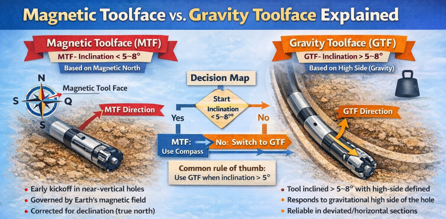
Decision Map: Magnetic vs. Gravity Toolface
Magnetic Toolface (MTF)
When to use:
Inclination typically less than ~5–8°
Near-vertical sections or shallow build intervals
Early kickoff before the high side of the hole is defined
Reference frame:
Measured clockwise from magnetic north on the horizontal plane
Magnetometers in the MWD tool detect Earth’s magnetic field
May be corrected to true north using declination data
What it tells you:
The compass direction your bend is pointing
A reading of 0° means the bend is pointing toward magnetic north, 90° toward magnetic east, etc.
Advantages/limitations:
Reliable when the gravitational reference is weak
Subject to magnetic interference from casing or nearby wells
Not suitable once the inclination increases enough to define the high side
Gravity Toolface (GTF)
When to use:
Inclination generally above ~5–8°
Deviated and horizontal sections where the high side of the hole is unambiguous
Reference frame:
Measured clockwise relative to the high side of the hole
Accelerometers detect gravity to define the high-side (0°) and low-side (180°) of the borehole
What it tells you: How the bend is oriented relative to the hole geometry
0°: pointing up toward the high side — typically builds inclination
90°: pointing right — changes azimuth rightward
180°: down — tends to drop inclination
270°: left — changes azimuth leftward
Advantages/limitations:
Accurate when the borehole has a significant deviation
Insensitive to magnetic interference
Requires a clear high-side orientation to interpret correctly
Frequently Asked Questions
Why not use magnetic toolface throughout drilling?
Magnetic toolface becomes less reliable at higher inclinations because gravitational forces clearly define the high side of the hole, making GTF more meaningful and less affected by magnetic interference.
Can toolface be measured without MWD?
Yes — single-shot and wireline tools can measure toolface, but they lack real-time updates and generally are less efficient than MWD during active steering.
Does gravity toolface require a specific BHA orientation?
Accuracy in GTF depends on clear detection of the high side via accelerometers, which is typically robust once the inclination exceeds a few degrees.